Metal lathe
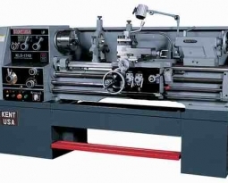
The design of lathes can vary greatly depending on the intended application; however, basic features are common to most types. These machines consist of (at the least) a headstock, bed, carriage, and tailstock. Better machines are solidly constructed with broad bearing surfaces (slide-ways) for stability, and manufactured with great precision. This helps ensure the components manufactured on the machines can meet the required tolerances and repeatability.
Headstock
Headstock with legend, numbers and text within the description refer to those in the image
The headstockhouses the main spindle speed change mechanism and change gears . The headstock is required to be made as robust as possible due to the cutting forces involved, which can distort a lightly built housing, and induce harmonic vibrations that will transfer through to the workpiece, reducing the quality of the finished workpiece.
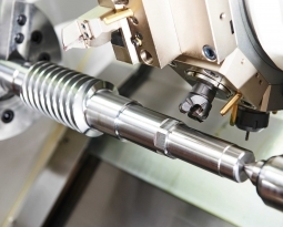
The main spindle is generally hollow to allow long bars to extend through to the work area. This reduces preparation and waste of material. The spindle runs in precision bearings and is fitted with some means of attaching workholding devices such as chucks or faceplates. This end of the spindle usually also has an included taper, frequently a Morse taper, to allow the insertion of hollow tubular (Morse standard) tapers to reduce the size of the tapered hole, and permit use of centers. On older machines (’50s) the spindle was directly driven by a flat belt pulley with lower speeds available by manipulating the bull gear. Later machines use a gear box driven by a dedicated electric motor. A fully ‘geared head’ allows the operator to select suitable speeds entirely through the gearbox.
Beds
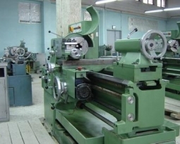
The bed is a robust base that connects to the headstock and permits the carriage and tailstock to be moved parallel with the axis of the spindle. This is facilitated by hardened and ground bedways which restrain the carriage and tailstock in a set track. The carriage travels by means of a rack and pinion system. The leadscrew of accurate pitch, drives the carriage holding the cutting tool via a gearbox driven from the headstock.
Types of beds include inverted “V” beds, flat beds, and combination “V” and flat beds. “V” and combination beds are used for precision and light duty work, while flat beds are used for heavy duty work.[citation
When a lathe is installed, the first step is to level it, which refers to making sure the bed is not twisted or bowed. There is no need to make the machine exactly horizontal, but it must be entirely untwisted to achieve accurate cutting geometry. A precision level is a useful tool for identifying and removing any twist. It is advisable also to use such a level along the bed to detect bending, in the case of a lathe with more than four mounting points. In both instances the level is used as a comparator rather than an absolute reference.
Feed and lead screws
The feedscrew is a long driveshaft that allows a series of gears to drive the carriage mechanisms. These gears are located in the apron of the carriage. Both the feedscrew and leadscrew are driven by either the change gears (on the quadrant) or an intermediate gearbox known as a quick change gearbox or Norton gearbox. These intermediate gears allow the correct ratio and direction to be set for cutting threads or worm gears. Tumbler gears (operated by) are provided between the spindle and gear train along with a quadrant plate that enables a gear train of the correct ratio and direction to be introduced. This provides a constant relationship between the number of turns the spindle makes, to the number of turns the leadscrew makes. This ratio allows screwthreads to be cut on the workpiece without the aid of a die.
Some lathes have only one leadscrew that serves all carriage-moving purposes. For screw cutting, a half nut is engaged to be driven by the leadscrew’s thread; and for general power feed, a key engages with a keyway cut into the leadscrew to drive a pinion along a rack that is mounted along the lathe bed.
The leadscrew will be manufactured to either imperial or metric standards and will require a conversion ratio to be introduced to create thread forms from a different family. To accurately convert from one thread form to the other requires a 127-tooth gear, or on lathes not large enough to mount one, an approximation may be used. Multiples of 3 and 7 giving a ratio of 63:1 can be used to cut fairly loose threads. This conversion ratio is often built into the quick change gearboxes.
The precise ratio required to convert a lathe with an Imperial (inch) leadscrew to metric (millimeter) threading is 100 / 127 = 0.7874… . The best approximation with the fewest total teeth is very often 37 / 47 = 0.7872… . This transposition gives a constant -0.020 percent error over all customary and model-maker’s metric pitches (0.25, 0.30, 0.35, 0.40, 0.45, 0.50, 0.60, 0.70, 0.75, 0.80, 1.00, 1.25, 1.50, 1.75, 2.00, 2.50, 3.00, 3.50, 4.00, 4.50, 5.00, 5.50 and 6.00 mm).